
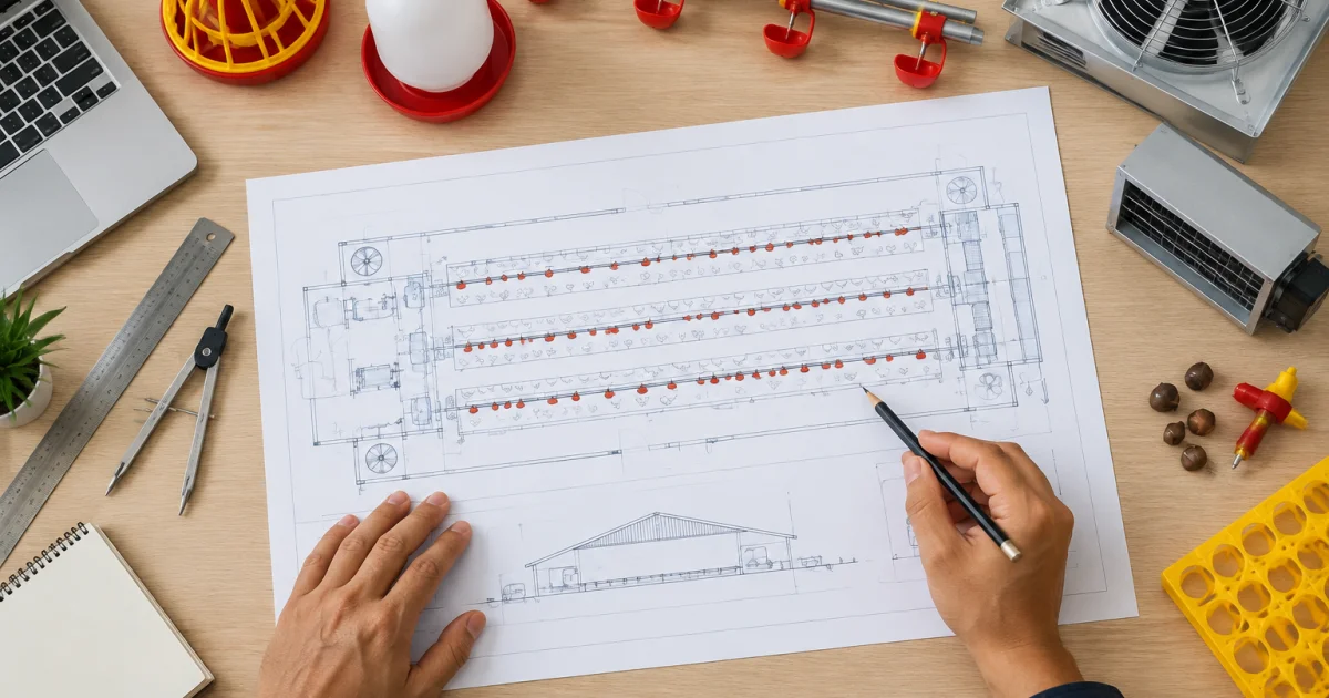
When you build or expand a commercial poultry house, the shell is only part of the job. The real risk (and cost) is mismatched systems: housing, feeding, drinking, ventilation, and (for layers) egg handling. A clear poultry equipment layout plan helps you confirm bird flow, staff access, biosecurity routes, and upgrade paths before you pour concrete or order equipment.
Use the workflow below to produce a practical, quotable plan—without late redesigns.
Step 1: Define the production brief (the “inputs” your layout must satisfy)
Start with a one-page brief so the drawing supports real performance and future expansion.
- Bird type and housing concept: layer cage (A-Frame, MBB, aviary), breeder, or broiler floor. This drives aisle widths, service routes, and whether egg handling is required.
- Capacity and phasing: target headcount now and in phase 2. Identify expansion points (extra fans, an additional feed silo, spare controller channels).
- Labour model and automation goals: staffing per shift and which tasks to automate (feeding, egg collection, manure removal, climate control).
- Utilities and constraints: power, water source/pressure, drainage, and practical locations for silos and service rooms.
- Site realities: orientation, prevailing wind, vehicle access, and clean/dirty (biosecurity) routes.
Deliverable: a short brief plus a must-have list (e.g., central service corridor, egg elevator-ready space, allowance for added fan capacity).
Step 2: Draw the building footprint and lock in fixed zones first
Work on a scaled plan with consistent units. Include structural elements early because they become immovable constraints.
- Overall dimensions: length, width, eave height, roof profile (affects ventilation and routing).
- Columns/frames/bracing: show spacing and exact positions to avoid conflicts with drives, belt heads, and conveyors.
- Service rooms: controller/electrical room, pump/medication area, storage—placed to reduce unnecessary traffic through the bird area.
- Loading/collection side: define where eggs (layers) or birds (broilers) exit and keep traffic as one-way as practical.
Tip: mark early “no-go” zones such as door swings, sanitation points, and external vehicle turning space.
Step 3: Place the core housing layout (cage or floor) and design the aisle logic
Housing geometry sets everything else. Finalise it before you route feed, water, or wiring.
For layers: choose the cage concept and aisle widths
Start with row count, tier count, and end clearances.
- Row orientation: typically along the house length for simpler routing and more consistent airflow.
- Aisles: include a main service aisle plus inspection/maintenance aisles sized for safe movement and access to feed/manure/egg components.
- End clearances: reserve space for drive stations, tensioning, turns, and motor/gearbox access (feeding and egg systems).
If you’re comparing options, an A Frame layer cage system can make early scaling straightforward, but you still need realistic drive and service space.
For broilers: define the usable floor area and equipment lanes
- Feed line lanes: keep straight, symmetrical lines for even feed distribution and simpler winch points.
- Drinker line lanes: plan for height adjustment and flushing access.
- Brooding/partition zones: show temporary curtains and heater placement if part-house brooding is used.
- Catch-out routes: maintain clear paths for depletion and catching teams.
Deliverable: a scaled “housing layer” drawing with cage blocks or floor zones, labelled aisles, and end clearances.
Step 4: Lay out feeding and feed storage as one connected system
Feeding is a chain: silo location → auger route → hopper(s) → distribution to each row/line. Plan it as one system to avoid daily operational issues.
4.1 Choose silo placement and service access
- Truck access: allow safe approach without crossing clean zones.
- Maintenance clearance: provide access for ladder work and auger servicing.
- Site conditions: avoid flood-prone spots and protect discharge areas where possible.
4.2 Map the feed delivery route into the house
Draw the full route with arrows.
- Minimise bends and crossings: reduces wear and simplifies troubleshooting.
- Keep drives accessible: avoid placing drive units where technicians cannot safely reach them.
- Coordinate heights: confirm the auger path clears trusses and does not clash with ventilation or cable trays.
If you plan auger-based distribution, reserve straight routing and service points for a flex auger run, including entry point and drive/control locations.
4.3 Inside-house feeding layout checks
- Line spacing: ensure every row/lane is served without dead zones.
- End units: allow clearance for tensioning and cleaning access.
- Power drops: mark motor locations so electrical planning stays realistic.
Deliverable: a “feeding layer” drawing showing silos, auger paths, drives, and each line served.
Step 5: Plan drinking lines with pressure zones, flushing, and hygiene in mind
Water layout mistakes show up immediately as wet litter (broilers) or uneven consumption (layers/breeders). Plan routing and water management together.
5.1 Decide water entry point and treatment/medication zone
- Entry and isolation: show main valve, filter, meter near the service boundary.
- Medication point: keep accessible and out of dust-heavy traffic.
- Drain/flush handling: define where flush water goes to avoid standing water near the house.
5.2 Draw drinker lines and pressure management
- Line routing: keep straight runs, ideally parallel to feeding lines.
- Regulators and zones: use multiple pressure zones in long houses to reduce variation at the far end.
- Service access: leave space to inspect nipples, adjust height, and service regulators.
For realistic line counts and typical service points, review examples such as drinking systems for layers and Ziggity options—even if brand selection comes later.
Deliverable: a “drinking layer” drawing with water entry, regulators, flush points, and routing.
Step 6: Ventilation and climate control: place fans, inlets, and airflow paths
Ventilation planning is about performance and maintainability. Placement depends on natural, cross, or tunnel ventilation.
6.1 Mark the ventilation concept and airflow direction
- Airflow path: draw arrows from inlets to exhaust points (or pads-to-fans in tunnel setups).
- Fan staging: plan minimum vs hot-weather capacity with grouped fans.
- Pressure/sealing allowances: reserve space for curtains/inlet mechanisms and ensure the building can seal where required.
6.2 Place fans and inlets without creating maintenance bottlenecks
- Fan clearance: keep service space for cleaning and belt/motor work, and avoid external obstructions.
- Inlet uniformity: distribute inlets to prevent short-circuiting straight to nearby fans.
- Cable/sensor plan: mark controller locations and approximate cable routes; place sensors in the birds’ zone (not near doors or drafts).
Treat the poultry fan layout as a major design item, not an add-on. For typical component scope, see climate control solutions.
Deliverable: a “ventilation layer” with fan banks, inlets/pads (if used), airflow direction, and controller/sensor positions.
Step 7: Egg handling layout (layers): plan the egg flow end-to-end
In layer houses, egg flow strongly affects labour, breakage risk, and scalability. Design it early.
7.1 Map egg flow from cage to collection point
- Collection direction: one end vs both ends.
- Transfer points: each belt-to-belt or belt-to-elevator transfer needs clearance and safe access.
- Work area: allocate space for checking/counting/staging away from dusty airflow paths.
7.2 Reserve space for egg conveyor and vertical transfer
- Conveyor runs: draw the route, supports, and access points.
- Elevator location: place where it connects cleanly to the outgoing line and can be safely inspected.
For planning around real footprints, reference typical egg conveyor and egg elevator configurations.
Deliverable: an “egg handling layer” showing conveyors, elevator position, collection area, and egg-out route.
Step 8: Combine layers into one coordinated plan and run clash checks
Overlay housing + feeding + drinking + ventilation + (egg handling). This is where conflicts appear—resolve them before requesting quotations.
8.1 Clash checklist (common problems to catch early)
- Physical clashes: auger through a truss, regulators blocking aisles, conveyor colliding with columns.
- Maintenance access: fans too close for belt service, motors located where safe access is impossible.
- People flow and biosecurity: staff forced through dirty zones or egg/bird routes crossing feed delivery paths.
- Electrical realism: no practical cable routes, controller room too far without planned conduits.
8.2 Create a quotation pack suppliers can actually price
- Scaled layout (PDF): key dimensions, aisle widths, equipment positions.
- Single-line routes: basic feed, water, and electrical zone diagrams.
- Equipment schedule: row/line counts, fan groups, controller scope, and future options (extra silo, added cooling pads, future egg line).
- Assumptions list: inclusions/exclusions and who commissions what.
Step 9: Validate the plan with a practical “day-in-the-life” walk-through
Do a quick operational simulation to confirm the plan works in real use:
- Morning checks: can staff inspect lines/cages without unsafe squeezes or restricted areas?
- Feed delivery: can trucks refill safely, and can staff reach blockages?
- Water management: can flushing and regulator checks happen without flooding walkways?
- Hot day response: can staff access fans, curtains, sensors, and controllers quickly?
- Egg collection (layers): does egg flow avoid tight turns, awkward transfers, or risky work positions?
Small changes here (door position, end clearance, service-room access) often prevent major commissioning problems.
Conclusion: A layout plan is your coordination tool—build it before you build the house
A commercial poultry house is a system-of-systems project. Planning housing, feeding, drinking, ventilation, and egg handling together reduces rework, protects maintenance access, and makes quotation comparisons more accurate. Build your plan in layers, merge them into one coordinated drawing, run clash checks, then finalise equipment scopes before foundations and installation begin.
Frequently Asked Questions
What should be included in a poultry house equipment layout plan for quotations?
Include a scaled building footprint with columns/doors, housing arrangement (cage rows or floor zones), feeding route from silo to lines, drinking line routing with regulators/flush points, ventilation fan and inlet locations with airflow direction, and (for layers) egg flow with conveyor/elevator positions. Add an equipment schedule (quantities and line counts) plus a short list of assumptions and exclusions.
How do I choose between a cage system and floor system when planning layout?
Start from your production brief: bird type, target capacity, labour plan, and whether you need egg handling. Cage systems usually require more detailed end clearances for drives, manure/egg belts, and service aisles. Floor systems need clear equipment lanes, brooding/partition zones, and catch-out routes. If you are uncertain, draft both at the same scale and compare aisle width, service access, and expansion flexibility.
Where should I place fans and inlets to avoid ventilation problems?
First decide the ventilation concept (natural, cross, or tunnel) and draw the airflow direction. Place fan banks so they can be serviced from outside and are not blocked by structures. Distribute inlets to avoid short-circuiting air straight to the nearest fan. Keep sensor locations in the bird zone (not next to doors or direct drafts) and plan cable/conduit routes early so installation remains tidy and reliable.
How much clearance do I need at the ends for feeding drives and egg conveyors?
You should reserve practical end space for drive units, tensioning points, turning components, and safe maintenance access. The exact clearance depends on the chosen equipment model and row/line count, so the safest approach is to request equipment footprints from the supplier during planning and reflect those dimensions on your drawing before finalising the building works.
Can I plan the layout now and add automation later?
Yes—if you design for it. Leave expansion points for extra fans, spare controller capacity, additional feed routes or silo space, and clear paths where an egg conveyor or elevator could run later. Also plan electrical distribution and cable routes with spare capacity so upgrades don’t require disruptive rework inside the house.
Get Tong Seh to Review Your Poultry House Layout Plan
If you’re planning a new build or expansion, Tong Seh can help you translate your footprint and production goals into a coordinated equipment layout covering feeding, drinking, ventilation and egg handling. With over 40 years of experience and local manufacturing capability, we support practical, automation-focused farm systems and custom configurations to match your capacity and workflow.
Share your building dimensions and target bird numbers, and we’ll advise on a layout concept and the right equipment scope to request accurate quotations.
Disclaimer:
The information provided in this article is for general informational purposes only. Readers are encouraged to consult with a qualified professional or contact Tong Seh for advice and solutions tailored to their specific needs. While we strive to provide accurate and up-to-date information, we cannot guarantee that it is entirely error-free. Tong Seh Industries Supply Sdn Bhd (TSIS) assumes no responsibility for any errors or omissions.